簡易頻譜分析儀 – SDR手指活用法


spectrum_cover


前言

SDR 手指除了可用來接收大氣電波的訊號外,還可作為一個廉價的頻譜分析儀 spectrum analyser,本文淺談一下。


首先,我們要釐清使用方法。一般接收大氣電波,SDR 手指天線端接到天線即可。而作為頻譜分析儀,則需直接輸入訊號。

在空氣中 pick up 電波,和直接 feed 入訊號是兩回事。空氣中的電波,訊號再強也很難損壞 SDR 手指前級電路。

但直接在 SDR 手指天線端 feed 入訊號,就可能會損壞 SDR 手指了。我們必需先預備一至兩組衰減器(attenuator) 。

說穿了也不外是一組電阻線路而己。我預備一組 –20dB,一組 -40dB。砌一組和砌兩組時間相若,有兩組有備無患。

20-40db_att

Courtesy of

 http://g7ltt.blogspot.hk/2014/08/20db-or-40db-rf-attenuator.html


電阻最好用 1%metal filmSMD 以降底 L 的影響。不過業餘用途用回普通的也不礙事。

a20_40_att


軟件使用

和一般接收大氣電波不一樣,我們需起用兼容 SDR 手指的頻譜分析軟件。原因簡單,以 RTL-SDR 為列,最多只能見2M 頻寬的東西。

而頻譜分析軟件,則會按用家設定從起始頻掃描到終點頻。所需時間按你的電腦速度,steps 間隔設定而不一。

SDR# 其實內置了 spectrum analyser 軟件 SpectrumSpy的,但只限其品牌的 airspy SDR 可用。

免費軟件 spektrum 簡單易用,掃描時間比其他同類軟件更快。本文以她為示範。

Spektrum link:

https://github.com/pavels/spektrum


初測

初測主要 set 起個陣。不外擔心兩件事。

偏頻,和訊號會否太強損壞 SDR 手指。

由於存在損壞變數,所以我用回上一代,已退役的 SDR 手指。

40dB 衰減器接到 SDR 手指的天線端,另一邊則是 RF 訊號。這時,一部日系手機絕是好幫手。原因簡單,頻率精準,諧波少,最重要是有 EL power 輸出。

spect_144640


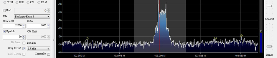
這是 TH-F7 串接 40dB 衰減器後的頻譜圖,效果理想。右上角顯示 max 頻率。假設日系機的頻率較精準,發射頻率144.640MHz,那顯示的就是偏頻後的頻率了。

freq_shift

要精準的可將這個 factor 加減到測試結果以獲得較準確的數字。

那如只有國產機 (一般 power 只有高底兩檔),怎辦

UV-5R 嘗試在 low power 串接 20+40dB 衰減器,得出這個結果。

uv_5R_20 40db


這應是輸出仍是太高所致。

幸好,不會燒掉 SDR 的前級。


sdr_copper

SDR 手指外包了銅片,是之後的事,希望降底一點雜紋。對實際效果沒幫助。


其他配備

初測只是釐清配置和設定。Feed 個手機訊號到 SDR 手指,實際作用不大。其他測試,我們起碼需配備一個噪聲訊號源。

噪聲訊號源,簡單來說,當 broad band noise 吧。他在整個理論頻寬也會有一個穩定波幅訊號。

網上有不小這些電路,主要是 zenertransistor 的組合。我試製了一個,效果強差人意。


diy_noise


無謂浪費時間,遂淘了一塊國產的 PCBA

noise_pcba

這個是國外業餘無線電界很普及的 noise generator,雖評語不高,原因不外波幅在不同頻率下不一,和產生高熱至死板等。只能說,幾十元的價錢,就是這種的貨色了。

我首要面對的是,給電後真是好熱,溫度計量度超過 50C。長時間使用,可考慮用散熱膠水將 heatsink mountPCB 底部。

Return loss bridge

return_losss


電橋自行製作不難,很適合工科同學實踐當中理論。問題是所需的磁環市面難找。所以還是淘寶搞掂算數。一般 500MHz 以下的不過百元。

return_loss_bridge

電橋的解剖圖,YouTube 圖片


我購入的號稱頻率達 2.5GHz,約二百多元。


Round 1 濾波器檢測


144_cavity_filter

這是一支 VHF band 的空腔濾波器。技術規格是讓 130-174MHz 通過。但有見過天線,濾波器圖表的應知,過程不會是 linear 的。所以我們可以用 spectrum analyser 檢視一下其頻率特性。

Noise generator 直駁 filter 一端,輸出直駁 SDR 手指,掃描一下 100-200MHz。得出其頻率響應圖。

144_filter


Round 2 天線響應頻率檢測

noise generator 接到電橋輸入端,輸出端接 SDR 手指。測試端接受測天線。


sh940_uhf

這是我的 Diamond SRH940 天線在 UHF 的頻率響應圖。

實測發現,所有受測的 V/UHF 天線,在 VHF 表現均不理想(頻率響應曲線太平坦)。這虛耗了不少時間。

初步認為是 noise generator 或電橋在 VHF 的反應問題。


總結

SDR 手指作為 spectrum analyser ,廉價之餘也能夠提供最起碼的頻率測試結果。

大家按自身需要配備合適的組件,也無需盲從本人的購置。

有時間,有零件的也可自行組裝有關的設備,學到的一定比齋買為多。

之後也希望以此平台作更多測試。

Posted in Research | Tagged , , | Leave a comment

A simple USB programming cable for Yaesu FT-90R


ft-90_cover

 This article describes how to make a USB programming cable for Yaesu FT-90R, which I did not find any information in Web.

It should work with other Yaesu handheld or mobile rig, which use similar protocol, such as FT-2600M, FT50, VX1R and VX5R .

The Yaesu FT-90R is compact but output max 50W, V/UHF mobile transceiver.

Yes, it is an old model, but it still available on eBay, as well as in Yahoo Japan bid market.

I bought a 2nd hand but in very good condition on 2 years before at eBay.

When got a new rig, the first thing faced is memory channel programming.

Manual input the channels is fine but not efficient. If it can be handled buy a computer program, it is better.

Almost all Yaesu series rig can be programmed the channels via computer.

However, the program is not included, it needs extra costs. The most popular 3rd party vender is RT systems, The software with programming cable costs US$ 49.

With help from the open source community, a free programming software CHIRP was developed. It is good, but it seldom to describe the programming cable schematic.

When searching programming information for the FT-90R, I just found an RS232 interface circuit for this purpose.

ft90rs232


I tried make one and connect it to my notebook via an RS232 to USB adaptor, but it does not work.

As most of modern computer no longer provides RS232 serial port. A USB type is more suitable.

I study above circuit and the interface port (mic jack) of FT-90R, I found:


ft-90micb

From the manual of FT-90R, Pin 2 is Data pin, Pin 4 is Gnd.

1/ the 9600 bps data pin should be a bi-directional pin for  TX/RX data.
2/ the level seems is TTL (5V).
3/ pull high to the tx pin seems need.

Such requirement similar to ICOM IC-7000 programming / CAT remote control cable. Here is the circuit:

Figure-1

I modify a USB to TTL cord, to test it works for Yaesu FT-90. The chip of the cable is PL-2308HX , not the expensive FTDI one.

ft-90_prog

The pull high resistor is a SMD one


YouTube Demo


Tested it worked on both upload and download memory channel information.


Conclusion

CHIRP and a simple USB programming cable formed a free programming platform for my Yaesu FT-90. The circuit should work for others Yaesu rig use similar protocol, just replace the connector to an appropriate one.

If the rig supports remote control, the cable should work as well.

Have fun.


Posted in English Articles, Research | Tagged , , , | 7 Comments